COMPLETE STATIONS
PUMP AUTOMATION STATION
The operation of pump stations is a multi-task procedure that ensures the station’s performance and the safety of equipment & personnel at a minimum cost. The operation of the pump station, in some mines, has not changed for decades and it has become less and less affordable. In fact, most mines that have automated their pump stations, did it by applying expensive technology, which provided the necessary functions at high capital cost and with great dependency on high-tech qualified personnel.
The Hydrocore™ Pump Discharge Control Valve is a new and innovative application of the Hydrocore™ range of valves and combines three basic principles as well as several unique features:

- Opens automatically on pump startup as a result of the pump’s discharge pressure acting on valve’s shuttle.
- Prevents pump surge conditions by maintaining a positive discharge pressure when the pump is running, irrespective of the discharge column fullness level.
- Closes automatically on pump stop as a result of the valve’s top compartment force, acting on the valve’s shuttle, against the pump’s reduced discharge pressure.
- Assists Hydrocore™ check valve on the pump’s discharge.
- Can prevent water hammer on pump trip or pump stop occurrences by utilizing an Hydrocore™ check valve.
- Prolongs the balancing disc life span by maintaining a positive discharge pressure when the pump is running, irrespective of the discharge column fullness level.
- The pump discharge control valve pneumatically, hydraulically or electrically (by the use of an electrical actuator).
Application
The Hydrocore™ shock prevention valve prevents the occurrence of water hammer when:
- The entire pump station trips.
- The last of the running pumps trips.
- A pump operator abruptly switches the last running pump.
Uniqueness
The Hydrocore™ shock prevention system is a unique solution for high-pressure vertical or inclined pumping

Column Draining
The Hydrocore™ shock prevention valve is used as the column drain valve, enabling cavitation-free draining of the pump discharge column.
Principle of Operation
The shock prevention valve instantaneously opens on pump trip occurrence, to enable a flow passage to the station’s reservoir and to avoid abrupt stoppage of the reversing flow, with no need for actuators, pilots, sophisticated instruments or an external power source.
The control system consists of:
- N/O timer switch closes on pump trip occurrence and reopens after a short interval.
- N/C Solenoid valve, causing the instantaneous opening of the shock prevention valve when the timer switch closes.
- The N/C solenoid valve closes after a short time interval and fluid entering slowly to the valve’s closing compartment causes the slow closing of the shock prevention valve.
Pressure transient following a pump trip
We have modelled a Standard Nozzle Check Valve (SNCV) to determine its Cv (see figures below). The table on the right shows the power penalty cost of a Hydrocore nonslam check valve (HC) versus a SNCV.
As is evident, the cost savings using a Hydrocore nonslam check valve versus a SNCV are astronomical even within the first couple of years. Assuming that the price of electricity is not going to go down in the future, those cost savings will only increase.
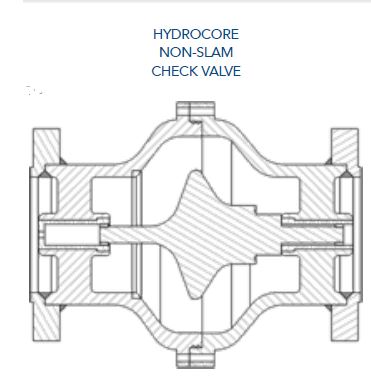

Pressure transient following a pump trip
The graphs demonstrate how the Hydrocore™ Non-Slam Check Valve compares to a regular check valve in the event of a pump trip. When the pump trips it creates a water hammer in the system which can cause havoc if the shock is not minimized.
With the use of a speed control orifice in the Hydrocore™ Non-Slam Check Valve, the shock of the water hammer (in the event of a pump trip) is minimized
greatly, due to the speed in which the check valve closes. In comparison, a regular check valve does nothing to alleviate the shock in the system due to the fact that the valve closes instantaneously.

Objectives & Advantages
The automation of the operation of the pump station can be achieved by applying the minimum necessary high-tech equipment, for the purposes of:
- Automatic opening of the pump discharge control valve, on pump start-up occurrence.
- Automatic closing of the pump discharge control valve, on pump stops or pump trip occurrences.
- Prevention of water hammer on pump’s stopping or tripping occurrences.
- Maintaining of sufficient pump discharge pressure, regardless of the operating conditions, in order to:
- Prevent pump flow surge conditions.
- Reduce wear of the pump’s balancing disc.
- Reduction of the operating cost by optimizing the required manpower for the operation of the pump station, with regards to:
- Intensive-labour operating personnel.
- High-tech maintenance personnel.
- Reduction in the dependency of the mine on high-tech qualified personnel mostly because this type of personnel becomes less available and less affordable.
- Reduction of the running & maintenance cost, due to the:
- Reduction of potential damage to pumps and pipelines.
- Reduction of the maintenance cost of pumps, instrumentation and columns.

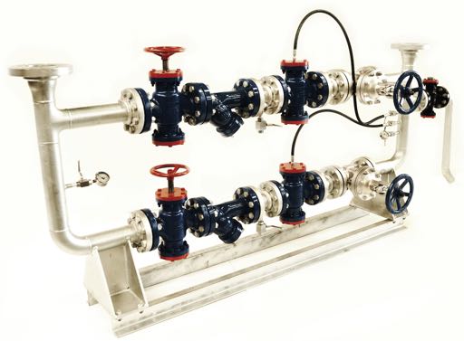
PRESSURE REDUCING STATION – A DUAL LEG OPERATION
The dual leg Pressure Reducing Station is a complete pressure reducing station that has a full operating leg backed by a full standby leg each leg consists of:
- Two hand-wheel operated valves to isolate a leg for maintenance.
- A strainer to prevent entrance of solids to the safety and control valves.
- A pressure reducing/control valve to maintain the required downstream pressure.
- A pressure relief valve is installed on the station’s outlet to prevent the rising of the downstream pressure above a specified safe level.
Optional
A safety shutdown valve may be added to each leg to shut off on high downstream pressure excess flow or any other safety conditions. The safety shutdown valve can be utilized for remote stop or start of the station.
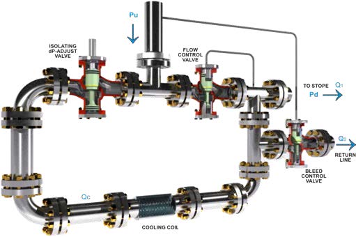
FLOW CONTROL STATION – STOPE ARRANGEMENT
Principle of Operation
The cooling coil control system maintains a constant differential pressure ‘dP’ across the coil, irrespective of the plant’s upstream pressure ‘Pu’ or the downstream water demand Q1. The bleed control valve maintains a constant differential pressure ‘dP’ across the coil.
Areas of Application
- The cooling coil control system maintains a constant flow through an underground cooling coil by: Maintaining a constant flow through the coil when the downstream demand is higher than the required flow.
- Discharging the excess flow when the downstream demand is lower than the required flow.
No actuator, pilots or pistons
The line-fluid pressure powers the valve with no need for external actuators, pilots, instruments or external power source.